The problem
Why underwater archaeology
Where we live, Western Australia, is surrounded by the ocean. With over 12,000 kilometres of coastline, over 1600 shipwrecks have been found, including the Batavia. This ship was lost in 1629, and when it was found, our state passed the first laws in the world to protect underwater heritage. The Batavia alone yielded 26,731 artefacts and 10,619 coins. So the problem SoftSense solves originates from our home.
Underwater archaeologists have a hard time recovering fragile artefacts from the seafloor, and the reason is that the manipulator arms bolted to remotely operated vehicles are built for industrial work, not precision handling. The standard arm has two rigid metal fingers, no force feedback, and little surface contact. That makes it clumsy with small, irregular, or brittle objects. When the wrong tool ends up in the wrong place, irreplaceable cultural heritage shatters on the seafloor.
Getting a maritime archaeology mission off the ground costs millions of dollars: vessel charter, crew wages, dive tickets, equipment shipping, port fees, insurance, fuel and permits. Months of planning go into a window of a few days on site. Even the recurring costs are punishing on their own: boat hire runs around AUD 5,000 per day and a four-person dive team is another AUD 1,200 per day, with dive gear maintenance and consumables on top.
The clock starts the moment you leave port.Patrick Morrison, WA Shipwrecks Museum
Against that cost stack, one piece of equipment failing on site can end the whole expedition. A gripper that shears a tooth and stops responding, or simply does not exist in the right specification on the boat, sends the team home with nothing. A two-thousand-dollar tool failure can waste a million-dollar mission. That asymmetry is what makes the gripper worth taking seriously.
Four identified problems
Talking to working archaeologists and subsea engineers, we pinned down four specific failure modes that the standard industrial gripper forces onto fragile recovery work.
- High risk of breakage. Industrial grippers apply force with no feedback channel back to the pilot. Thin pottery, coral, bone fragments and delicate shapes could crack if they are held too tightly.
- Poor grip on odd shapes. Flat metal jaws cannot adapt to curved, tapered or uneven artefacts. Items slip out, or cannot be lifted at all. The grippers in service today are designed for cylindrical T-bar handles on industrial tools, not for amphorae, bones or coral.
- Limited awareness for pilots. ROV operators cannot feel how much force the arm is applying, especially in low visibility water where the camera feed is the only signal.
- Cost and time pressures. A broken gripper or a missing tool means days of delay while a replacement is sourced. These failures slow missions down, push costs up, and can permanently destroy cultural heritage that has waited centuries to be recovered.
Why this matters now
All the wrecks we have found in Western Australia in the last four to five years are beyond recreational diving depths. The museum legally can't excavate them. The only way to recover something safely from 50 to 60 metres and beyond is a robot with actuator control.Patrick Morrison, Assistant Curator of Maritime Heritage, WA Shipwrecks Museum, 14 May 2026 site visit
Multibeam sonar surveys are turning up wrecks in the 40 to 100 metre range that were invisible to the previous generation of survey gear. There are more known sites than there is equipment to work them.
Who would use this
Our main user is a maritime archaeology team or research institution working from a small inspection class ROV. The closest commercial reference is the Reach Robotics Bravo 7 manipulator family, which Fugro and Woodside use for offshore inspection in Western Australia. The same gripper architecture also fits marine biology, oceanographic research, environmental monitoring, and any subsea repair job where standard grippers cause collateral damage.
How we researched and refined the problem
We did not start from a gripper design; we started from the problem and narrowed it down through research and expert review. We studied real subsea recovery using marine archaeology papers, ROV gripper datasheets and museum recovery records. That let us map exactly why the claws in service today fail on fragile artefacts: uncontrolled crush force.
We started broad, at recover artefacts, and narrowed to the specific risk of crushing fragile objects, then refined again on materials, from titanium and aluminium to printable plastics, after expert input.
Our team
Each member owns at least one work package, and most own more than one.
| Member | Primary ownership this season |
|---|---|
| Kingsley Wong | Brainstorm innovations collaboration, meeting with companies, sponsorship outreach. |
| Andre Nijman | SoftSense innovation lead. FEA campaign covering finger structural, grip texture and motor study. Sponsorship outreach. Material reevaluation. This documentation. |
| Sean Chan | Team brainstorm, collaboration, business outreach, material organisation for innovation. |
| Oliver Liu | Robot CAD and mechanical build lead. Chassis and attachment design. Field practice coordinator. Co-owner on prototype builds v1 and v2, drivetrain T_safe fix, hyperbaric pressure test. |
| Subesh Sukumaran | Research lead: existing manipulator survey and case studies. Owns expert cold email outreach and follow-up letters. Patrick Morrison site visit attendee. |
| Yuxin Chris Wang | Bench testing operator: ran the four-finger versus two-finger trials with the bone, anchor, vase and chest objects, capturing the 26, 96, 411 and 288 gf data. |
| Aaron Zhang | Created diagrams to explain and communicate the innovation work, and put together summaries in the presentation. |
| Leven Shi | Owns the photo and video evidence trail across the season. Co-ran the four-finger versus two-finger trials, and chassis design. |
Decision-making protocol
Day-to-day technical decisions are made by the work owner. Owners commit to their workstream and report back at the next meeting. Whole-team decisions happen when a choice touches more than one workstream, such as a robot redesign that changes attachment mounts, a SoftSense material change that affects the build schedule, or a sponsorship that needs a logo on the team shirt. These go to a meeting vote with a simple majority. The mentors have observer roles but not voting roles.
The four innovations
SoftSense takes the standard ROV gripper and adds four innovations that each go straight after one of the four failure modes. We tested every one, and a working expert reviewed every one.
1. Adaptive soft-contact finger pads
The contact face of each finger is a soft, compliant TPU surface carrying a fine printed grip texture, so the arm no longer presses bare metal against the artefact. The soft TPU spreads the gripping force over a wider area and lowers peak stress on fragile material, while the texture keeps a secure hold on wet, slippery surfaces. Where a rigid jaw point-loads a 4 mm patch of pottery rim, the compliant TPU face spreads the same total force over roughly ten times the area.
2. Force feedback through the actuator
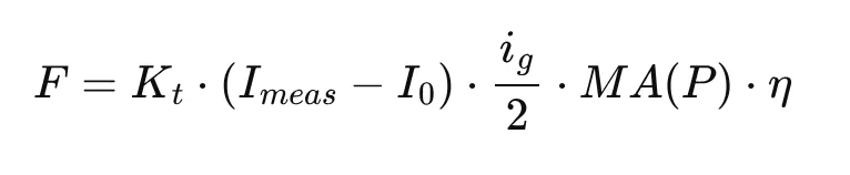
The gripper senses how hard it is squeezing without placing a single sensor on the fingertips. It reads the actuator's motor current, multiplies by the torque constant, and traces that back through the drivetrain to recover the tip force, the same method force-controlled industrial and surgical grippers from Maxon, Robotiq and Schunk rely on. That reading streams to the pilot's console without a break and feeds an auto-stop control loop that halts the actuator the moment the grip crosses a configurable threshold. The control code holds a different preset per artefact class: a low threshold for coral, another for bone, another for ceramic. The same motor-current limit that sets the grip force also caps the torque on the printed gears, so one channel is both the force command and the structural safety ceiling.
We did not begin here. Our first design put a calibrated pressure sensor under each pad. Two pieces of expert feedback moved the sensing into the actuator instead.
David Howard, in his regionals feedback, spotted a subtle confounder. As the gripper descends, ambient water pressure rises by roughly 1 atmosphere every 10 metres, so a fingertip pressure sensor would read squeeze when there is none, and would need a second ambient sensor plus a software correction just to recover the true value. Reading force from the motor current sidesteps the problem entirely: the current the actuator draws tracks how hard it pushes the object, not the water column above it.
Patrick Morrison raised a second concern at our 14 May site visit that pointed the same way. Any foam or gas-filled pad compresses with depth as the air pockets inside it shrink, so a pad-based sensor drifts as the dive gets deeper.
Force feedback is essential. Most industrial archaeological arms have it. Without it, you crush things and don't know about it.Patrick Morrison, WA Shipwrecks Museum
3. Self-morphing TPU fingers
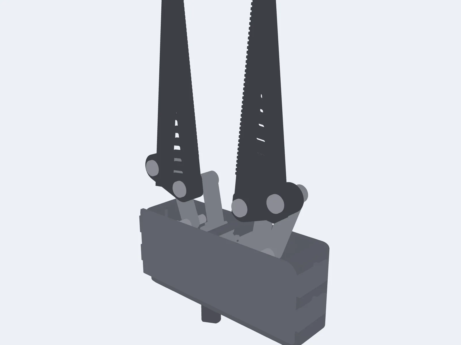
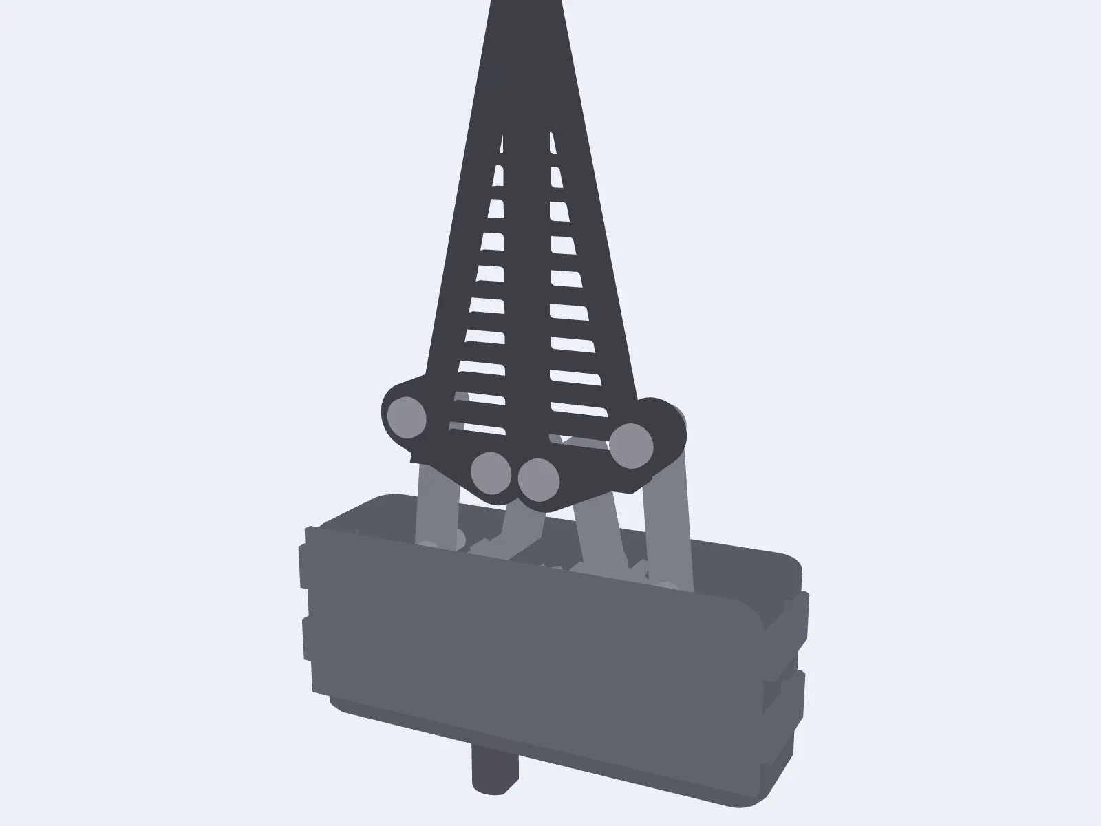
Each finger is a passive Fin Ray compliant truss printed in TPU. When the contact face presses against an object, the internal ribs make the whole finger curl inward and wrap, so it conforms to whatever shape it meets, whether a cylinder, a square block or an irregular fragment, instead of touching in one narrow band. The finger morphs to the object on its own, with no motor, tendon or moving part at the fingertip to seize underwater. More contact area at the same total force means lower local pressure and less crush risk, and the self-morphing wrap also forgives imprecise placement by the ROV pilot.
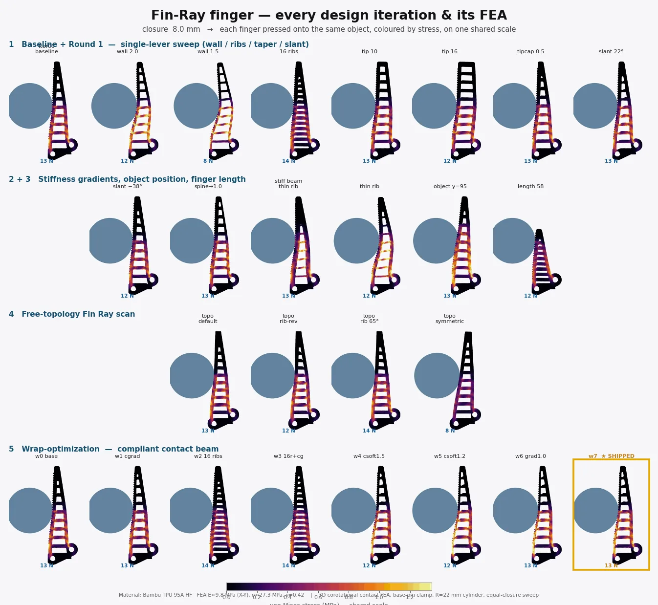
This is the innovation we proved hardest in software. We ran a design search of roughly 70 FEA simulations across a battery of seven object shapes and sizes, confirmed the finger wraps along its whole face rather than point-poking, and held the peak stress far below TPU strength.
4. A cheap, kit-based, modular claw
The whole gripper is built as a swappable, 3D printed module. The structural body costs around USD 70 in filament, and because the costly actuator is reused from module to module, a complete first-build kit runs from roughly USD 560 with the value DYNAMIXEL XM540 servo up to about USD 1,310 with the IP68 XW540 at the top of our actuator ladder. Archaeologists can carry several spares onto a mission and swap a broken module in the field instead of waiting days for a replacement to ship. Because the parts are 3D printed, the crew can bring a small printer on the support vessel and run off a custom grip or a new tool on deck while the dive plan keeps going.
The biggest cost in archaeology is time. Stick with cheap 3D printed parts. Anyone can buy filament anywhere, and the whole thing can be manufactured anywhere like a kit.Tim MacDonald, subsea engineer, Inkfish
The mechanism in detail
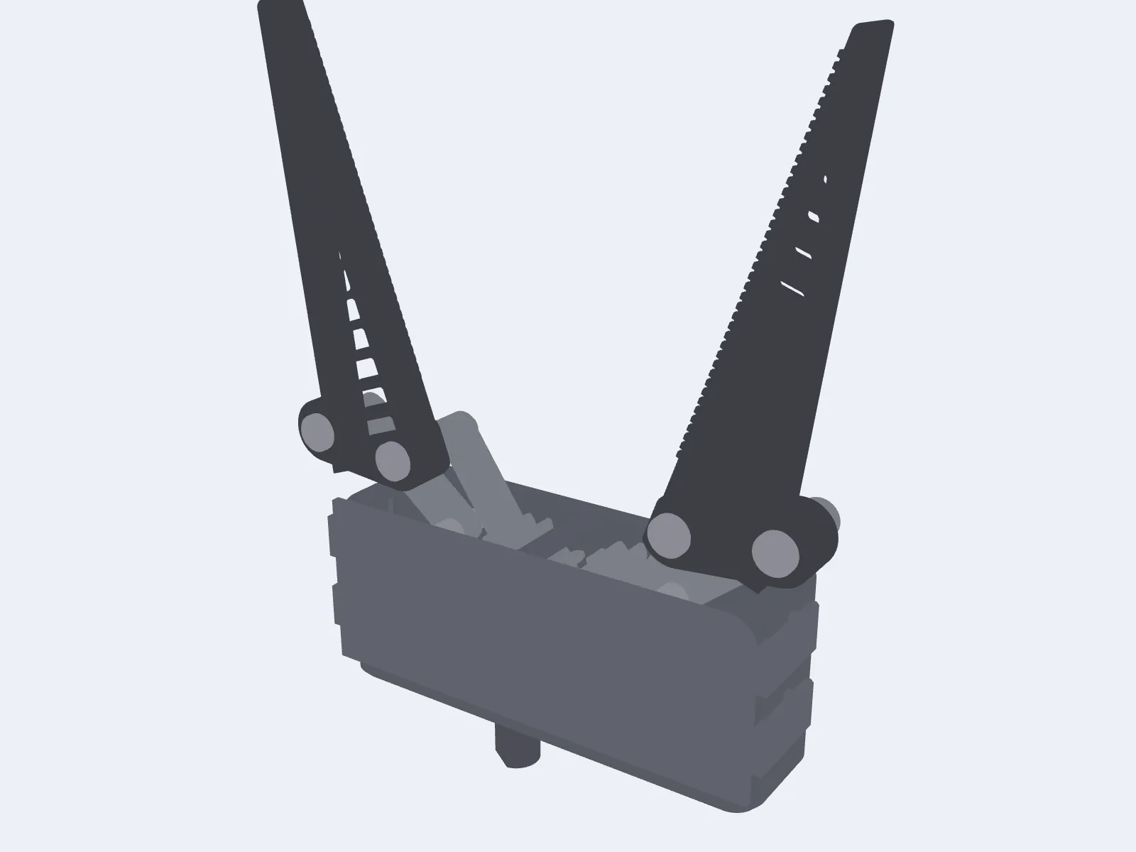
The end effector has a single degree of freedom. One input shaft rotates, and both fingers open and close symmetrically, splaying outward as they open to give a funnel-mouth catch. Everything else follows from that one rotation.
Drive chain
Two equal spur sector gears mesh on the centreline. The left sector carries an integral crown gear on its top face. A small spur input pinion on a vertical shaft drives that crown, a right-angle stage that lets the drive shaft exit out of the housing bottom. From the operator's side, the gripper has one input shaft going in and two symmetric fingers coming out.
Each sector gear doubles as the crank of a non-parallelogram four-bar linkage. The finger is rigid with the coupler. The link lengths give a translate-apart motion plus roughly 18 degrees of outward splay across the travel, and we sized them so the transmission angle stays well clear of any dead point, varying from 71.7 to 34.6 degrees across the open stroke.
Fingers and enclosure
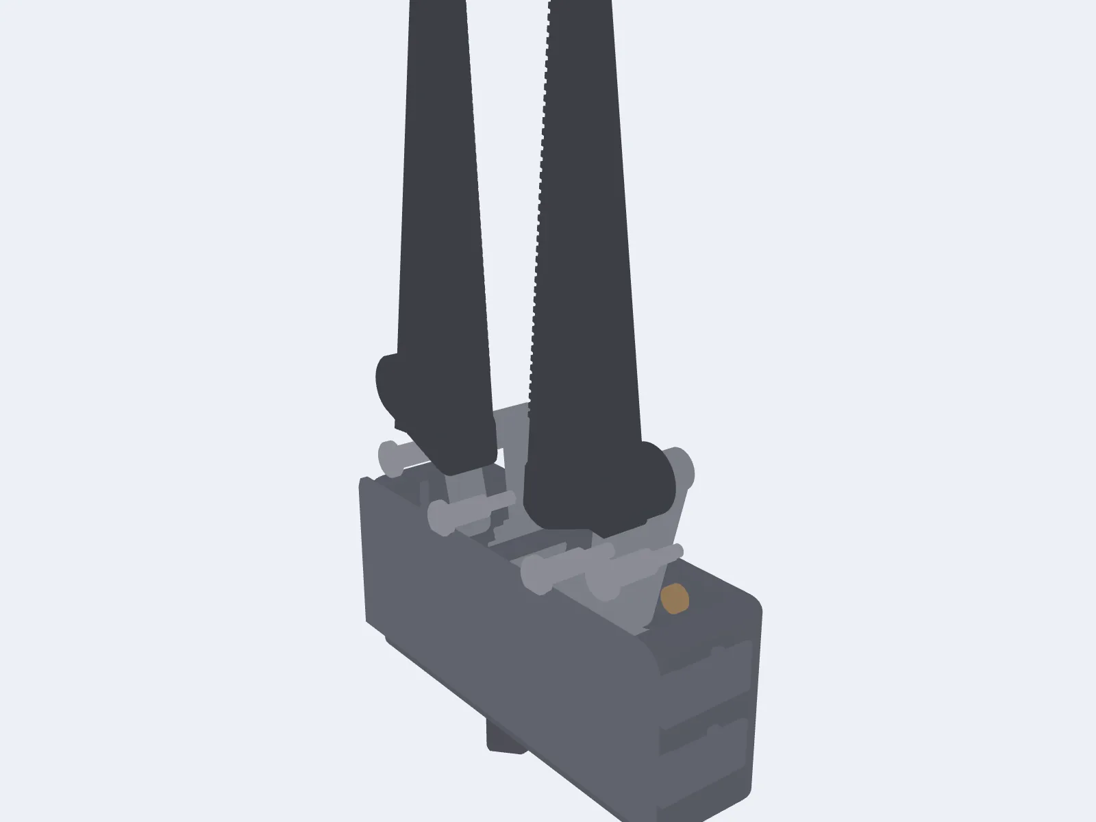
Each finger is a passive Fin Ray compliant truss in TPU. The architecture is a thin contact beam at 1.2 mm, a sharply tapered compliant spine at 1.8 mm, and 14 fine 1.6 mm slanted ribs with hollow cells. We checked that the two TPU fingers build as valid solids with zero interference at the closed pose at every finger scale we ship.
The enclosure is a single open-front housing with a snap-on front cover. Inside sit the two sector gears, the four-bar links and the crown-pinion stage. Outside are the M4 bottom mounting flange, the vertical input shaft, eight drain and flood paths, four snap-clip windows, the two top slots where the link arms exit, four axle bore floods through the back wall, and three 1.8 mm cover vents. Every part is a single solid with exactly one shell. There is no enclosed void anywhere in the assembly, and that is what makes the design safe to flood.
Finger structural FEA
We did not want to print a hundred fingers and snap them one by one in a bucket of water. That is slow, expensive, and biased toward the shapes we happened to think of first. So instead we built a physics model of the finger and ran a design search through it, scoring every candidate against a battery of objects, and we only committed to a geometry once it won in software and survived independent validation.
Dead ends we can show
The first dead end was a concave contact face matched to the object. The reframe that followed was that universality is a measurement gap, not a shape problem.
The second dead end was the flexure family, ruled out with data. The contact-notch flexure produced the only real circle wrap we saw in wave one, but the grip jumped around chaotically between 0 N and over 100,000 N at adjacent 0.25 mm steps.
The finalists and the shipped geometry
| Candidate | Full battery score | Notes |
|---|---|---|
| Production finger (w7 baseline) | 0.559 | Starting point. Wraps the 44 mm square but nothing else. |
| FULL_w2a05 (16 ribs, dir +1) | 0.602 | Better than baseline; the rib-direction lever helped a little. |
| FULL_w2c06 (blade length 76 mm, angle 32°) | 0.575 | Shorter blade did not generalise across sizes. |
| FULL_w2d05 (tapered spine + thin contact face) | 0.652 | The winner. 17% gain on the universal score. |
The shipped finger geometry is 14 ribs at 38 degrees with the reversed slant direction, a 1.2 mm contact beam, a 1.8 mm spine, 1.6 mm ribs and a 2 mm tip width with a sharp taper. Verified after the port: both fingers build as valid solids, there is zero finger-to-finger interference at the closed pose, and the four-bar closure is unchanged from the baseline.
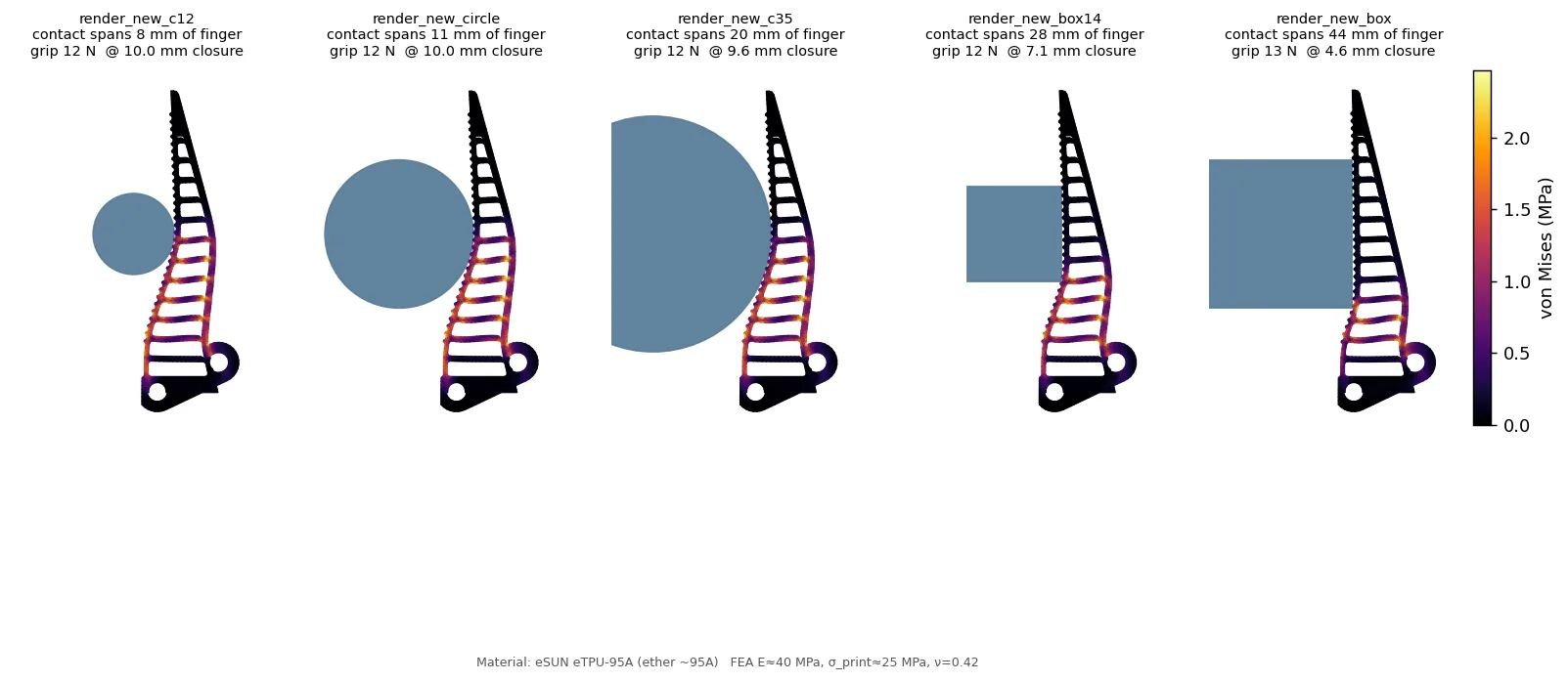
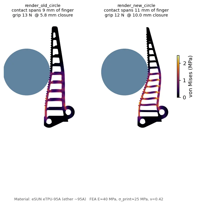
The result at equal 12 N grip
| Object | Old finger (arc / CoV) | Shipped finger (arc / CoV) | Change |
|---|---|---|---|
| Cylinder Ø24 | 2° / 0.45 | 2° / 0.71 | similar contact |
| Cylinder Ø44 | 7° / 0.74 | 17° / 0.84 | about 2.5x contact arc |
| Cylinder Ø70 | 11° / 0.68 | 21° / 1.12 | about 2x arc, less even |
| Square 28 mm | 1° / 0.83 | 87° / 0.98 | now wraps it, was a near-miss |
| Square 44 mm | 88° / 1.23 | 87° / 1.00 | wraps, more even |
| Universal score | 0.559 | 0.584 | +4.5% aggregate |
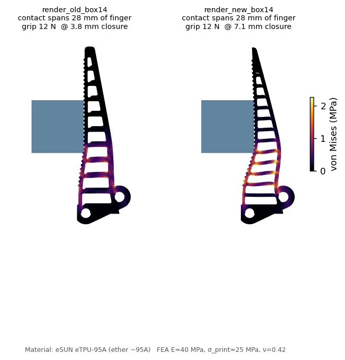
The old finger's grip swung by 7 times with object height, a stiffness-gradient artefact. The shipped finger grips every object at a consistent 12 N at the test load. The old finger only wrapped one square size; the new one wraps both. On round objects the contact arc roughly doubles.
Ceilings
Two formulations agree to order of magnitude on the fragility metric. A 2D plane-strain finite-strain solve and the 3D corotational solve both produce peak von Mises around 2.7 MPa at the 12 N stress-probe load. These are not the same problem, so this is a cross-formulation consistency check, not an independent re-derivation.
A locking-stable re-run of the 2D precursor showed that the linear-element solver under-reports peak von Mises by about 50 per cent at 12 N. So the headline 6.2 to 9.4 times margin is optimistic. A locking-free reading is closer to 4.1 to 6.2 times at 12 N. The design call does not change, because margins at the actual operating force are still around 120 to 300 times, but we corrected the absolute fragility number.
Choosing the grip surface
Once the finger geometry was locked, we still had to sort out the actual contact surface, the micro-relief that decides whether a finger catches on a wet object or slides off it. The finger structural FEA cannot answer that: it has no friction model and no fluid model. So we set up a second campaign with its own model, its own validation gates, and its own candidate list. The TPU we print the fingers in comes off the print bed with a glossy, low-friction skin.
Validation 1: the literature gate
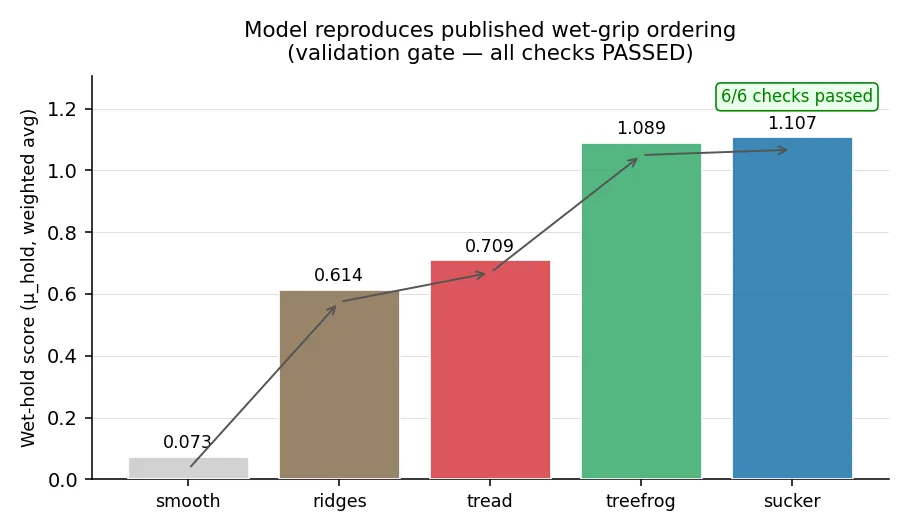
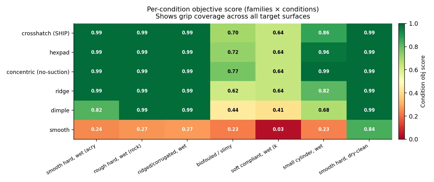
Before we trusted the model to rank anything, it had to reproduce the published wet-grip ordering of five real patterns. The model works out each pattern's wet holding coefficient and asserts six orderings. All six pass.
The texture sweep
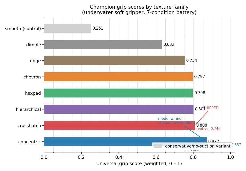
We ran seven texture families in parallel: ridge, crosshatch, chevron, hexpad (tree-frog), concentric (octopus sucker), dimple and hierarchical. Each family had its own parameter ranges and ran an inner sweep over its full parameter space at 0.1 mm resolution, then refined around its best score with a finer mesh. Together the seven families produced more than 700,000 model evaluations.
Validation 2: the sensitivity sweep
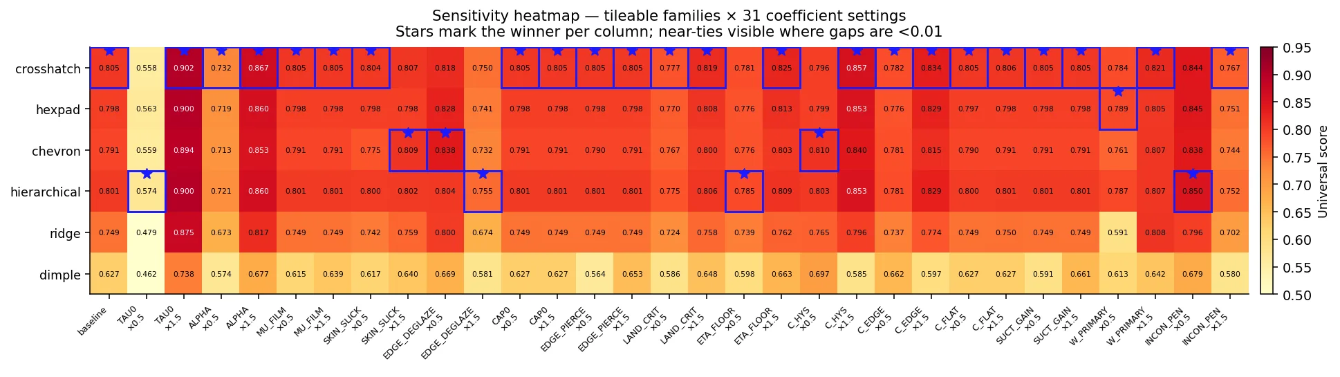
The central risk of a surrogate model is that family X wins might just reflect the numbers we chose. So we perturbed every coefficient to 0.5 and 1.5 times and, at each of 31 settings, re-optimised all seven families and recorded the winner.
The physical ceiling and the override
Concentric is the model's invariant winner, and we did not ship it, for two reasons. First, it cannot tile the finger blade: the contact face is about 72 mm by 10 mm, and at a 1.4 mm ring pitch at most one full rosette fits across the width. The model has no tileability term, so this is a missing-physics override, applied externally and on purpose. Second, its remaining lead leans on a speculative micro-suction term, which a 0.16 mm layer FDM TPU cavity cannot actually sustain.
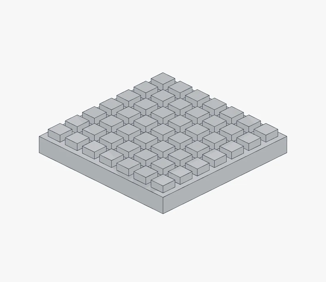
Among patterns that actually tile the blade, hold up without speculation, and print reliably, crosshatch is the empirical winner at 23 of 31 settings. That is what ships.
The motor study
Alongside the judging story we chased a deeper engineering question: could the actuator's own current draw stand in for the per-pad pressure sensors entirely, so there is no fingertip electronics at all? The answer turned out to be yes, with a real cost.
The principle
Force-controlled industrial and surgical grippers do not put strain gauges on every fingertip. They read the motor current, multiply by the torque constant, trace it back through the drivetrain, and recover an estimated tip force. For an underwater tool the payoff is hard to argue with: no fingertip wires running through a flexing TPU finger, no fingertip connector to flood, no separate analogue front-end to seal.
If you have a force sensor in the motor, you've replaced one of the worst sealing problems with one of the easier ones.
The actuator ladder
The selection sweep puts different actuator classes on top depending on depth. Same gripper body, same coupler interface, just a different drive.
| Tier | Actuator | Price (May 2026) | Why |
|---|---|---|---|
| Primary | DYNAMIXEL XW540-T260-R | USD 1,242 (AUD 1,925) | IP68 body, around 1.9 N·m, RS-485 bus, native present current at 0.005 N·m per step held cleanly at stall. |
| Value | DYNAMIXEL XM540-W270-R | USD 494 (AUD 766) | Same bus, identical telemetry, more torque. Drop-in replacement; the only difference is no IP68 body, which is moot inside the canister. |
| Deep-budget | Feetech STS3250 | EUR 64 (AUD 110) | Bought for the prototype. 4.9 N·m stall with load, position, voltage and temperature feedback; the load percentage is the torque proxy. |
| Rock-bottom | Feetech STS3215 | EUR 26 (AUD 44) | Same bus at 2.94 N·m stall. Continuous 0.98 N·m sits below the design target but above the floor; adequate for intermittent grip-and-hold. |
| Fallback | Magnetic-coupling dry-pod | Build | No shaft penetration; depth set only by static pod seals; pole-slip torque is a built-in force limiter. |
Limits of the sensor
- Force only, no contact location. Motor current is one aggregate number. It cannot say where on the finger the contact sits, and it cannot map pressure across the face.
- Relative until calibrated, and per unit. The torque constant varies 5 to 10 per cent unit to unit.
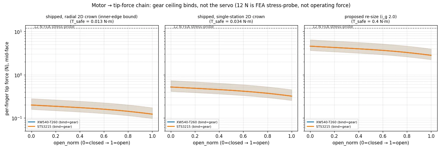
- Gear-ceiling-bounded. The sensed and commandable force is capped by the safe gear torque. The sensor is most useful precisely as the limiter that keeps the printed gears alive.
Where the per-pad sensors still win: they give four spatially resolved readings, one per fingertip. For the archaeological use case, where the operator needs to know which finger is overloaded, the per-pad sensors carry information the motor-current chain throws away.
The drivetrain limit
The compact right-angle crown and pinion stage is the binding structural limit of the entire gripper.
At the small radii the housing allows, the printed teeth carry far less torque than a 12 N stress-probe grip would need. We found this in the gear FEA. The fix has three parts: face-width strengthening, which is done and build-verified; a module and radius re-size, which is a proposed engineered target that still needs CAD clearance validation; and the motor current limit holding the safe ceiling in firmware.
We also have to flag two failure modes in our own method. The earlier framing presented a Lewis form-factor check against the FEA as cross-validation. It is not, because Lewis assumes an involute spur tooth and ours are straight-flank face teeth. Two wrong models that agree are not the same as one right model being confirmed. Second, the crown gear is a 3D problem, not a 2D plane-stress tooth, and the 2D solver catches none of the radial sweep, load split or disk-bending compliance. We added a radial variant that runs the same 2D FEA at five radial stations and takes the worst one, which tightens the single-station ceiling by 2.6 times.
| Ceiling | Per-finger force band |
|---|---|
| Radial 2D crown bound (binding) | 0.14 to 0.28 N |
| Single-station 2D bound | 0.35 to 0.73 N |
| Proposed re-size | 4.2 to 8.7 N |
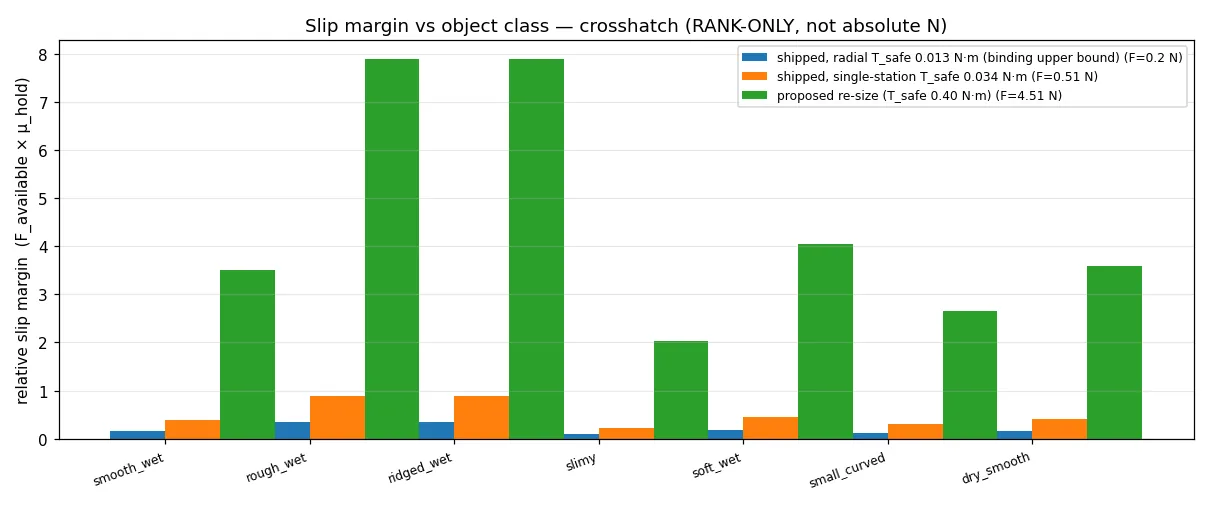
We kept the 24 to 9, or 2.667 to 1, ratio on purpose. The rock-bottom budget servo sets the binding floor: at 2.667 to 1 it reaches 12 N at the tip continuously, and dropping to 2.2 to 1 takes it to about 11.4 N, where the budget option no longer hits 12 N. The real change here is engineered teeth and a derived current ceiling, not a ratio tweak.
Three consequences follow. 12 N is a stress-probe load, not a structural mandate. The motor current limit enforces the safe torque in firmware, and it is mandatory on every servo in the ladder because their stall torques beat it by 10 to 30 times. And the bench test is the only true ceiling, because both 2D bounds are upper bounds.
Materials and printing
Why we are 100 per cent polymer
Galvanic corrosion has nothing to bite on in our gripper, because there is no metal anywhere inside it. Every pin, every snap, every gear, every shaft is printed. The only metal in the whole system lives inside the user's actuator canister, isolated from the seawater. That takes a whole class of failure modes off the table before it can even start.
Zero bought hardware inside the gripper. No screws, no nuts, no bolts, no bushings. 17 printed parts, fastener-free assembly, tool-free disassembly.
The final build
The production build uses three materials, each assigned by what it has to do structurally. The enclosure, front cover, drive arms, input pinion shaft, followers and axle dowels are PA12-GF. The two fingers are TPU 95A HF. The four finger snap pins are PETG-HF. Total filament comes to about 120 to 175 g of PA12-GF, 50 to 70 g of TPU and 4 to 8 g of PETG-HF.
Why PA12-GF for everything rigid. PA12 is the lowest-water-uptake engineering nylon available. Saturated seawater absorption sits at about 0.7 to 1.2 per cent, and the glass fill brings that down further. It does not hydrolyse and it holds tight dimensions after long immersion. The 30 per cent glass fill gives roughly 3.5 to 5.5 GPa modulus and low creep.
PA12-GF replaces an earlier spec for carbon-filled Nylon 12, which needs a 45 to 60 degree heated chamber that the Bambu P1S we print on cannot hold. Without the chamber it lays down with poor inter-layer adhesion and warps as it cools. We will be honest that PA12-GF is also marginal on the P1S: glass-filled nylon is warp-prone on the larger parts, so it wants a closed chamber, a brim, and a 260 to 280 degree nozzle over a 90 degree bed with glue stick.
Why PETG-HF only for the finger snap pins. Glass fill trades ductility for stiffness, and the barbed split-tip pin that secures the fingers has to flex inward as it passes through the receiving bore.
Why TPU 95A HF for the fingers. The Fin Ray grip principle is all about material compliance. The fingers have to flex visibly as they wrap.
Running it underwater
The seawater audit settles the chemistry, the buoyancy and the flooded geometry. The design consequence of the finger crush analysis is a procedure, not a redesign: submerge the gripper fingers-down and let it soak so the flood paths clear.
Patrick Morrison's checklist from the site visit maps onto the build one to one. His warning that foam and gas-filled pads compress at depth reinforced the move to motor-current sensing. His fail gripping, not releasing point became the firmware holding-current threshold. His wet-connect advice fed the mounting interface. His 2 to 5 kg payload figure is the boundary we state. And his accept internal flooding, design around it advice matches our fully-flooded, no-sealed-cavity architecture.
ROV integration
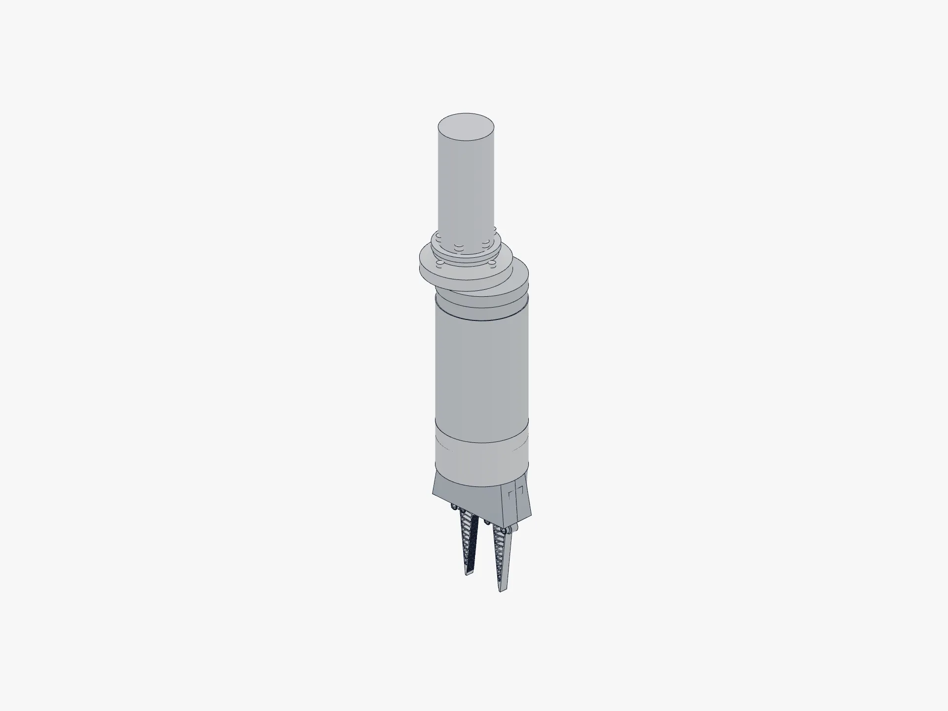
The gripper mounts through a common gripper-side mate, with adapters modelled for the Reach Robotics Bravo 7 wrist, ISO 9409-1 cobot flanges, BlueROV2 bottom panel, roof rack and payload skid mounts, and an ISO 13628 D-handle override for diver operation.
Two non-negotiables
- The primary tier still needs a thin pressure canister, even for the IP68 servo, because IP68 is rated for 1 metre of freshwater only while 30 metres is 3.1 bar plus seawater corrosion. The flooded gripper itself has no shaft seal and no dry cavity, so the sealing job falls entirely on the actuator.
- The motor current limit must be set to the safe gear torque in firmware. Without it, a strong servo's stall torque shears the printed teeth.
The control electronics
Rather than a topside computer and a tether junction box, we put the whole controller on one small board that travels with the gripper: a Waveshare General Driver for Robots, built around an Espressif ESP32-WROOM-32.
The board boots into its own Wi-Fi access point, serves a phone web page, and is the servo's bus master, all at once. There is no router and no internet. You power it from roughly 12 V, it broadcasts a network, you join it from a phone, a captive-portal page opens, and you get open and close buttons with live position, load, voltage and temperature underneath. A 0.91 inch OLED on the board mirrors the network name, the IP address and the current position. This replaces an earlier Orange Pi single-board-computer controller we prototyped.
The controller is also where the actuator-as-sensor thesis becomes a real readout. It commands the servo and reads that servo's own load, voltage and temperature back over the same three-wire bus, so the force sensor is exactly the number this board already streams to the phone.
The open and closed positions ship as placeholders. On first run you move the gripper to its fully open pose and save it, then to fully closed and save that. Those values, along with move speed and acceleration, are written to non-volatile flash and survive power cycles, so the gripper is calibrated once on the dock and then just works.
What is proven: the firmware is written and compiles cleanly. It is not yet bench-validated on the board, which is on order. The bus pins, baud rate and protocol are taken from Waveshare's own firmware for this exact board, so they should be correct out of the box, and the open and closed directions are placeholders until calibrated on first power-up. Like the rest of SoftSense, the controller is offline by design.
Technology readiness and operating boundaries
At Woodside's request we say where SoftSense sits today on the NASA technology readiness level scale and what would move it forward. We sit at TRL 3 to 4. Levels 1 to 3 are done: the principle is established, the concept is specified, and there is a working scaled prototype with all four innovations integrated, bench-tested against the four-object artefact set. Level 4 is partially done, with FEA validating the fingers and the texture, and soak and hyperbaric tests scheduled. Level 5 requires a pool dive on a BlueROV2 chassis with a real artefact analog at depth. The valley of death that Woodside warned us about is the gap we are crossing right now.
| Parameter | Boundary |
|---|---|
| Operating depth | 0 to 50 m for the shipped configuration; the magnetic-coupling pod extends to 200 m or more as a future option. |
| Operating temperature | −2 to +30 °C water temperature, which covers WA continental shelf summer and Antarctic Peninsula summer. |
| Residency time in water | Continuous immersion up to 30 days per the soak-test result; rinse with fresh water between deployments. |
| Salinity | Full marine at 35 ppt to brackish; fresh water also acceptable. |
| Payload | 2 to 5 kg per the archaeology use case; structural test required to certify above 5 kg. |
| Grip force per finger | 0.14 to 0.73 N with the shipped gears, or 4.2 to 8.7 N with the proposed re-size. |
| Maintenance interval | Visual inspection every dive; pin replacement annually or after visible creep; finger replacement at 10,000 grip cycles or first visible TPU crack. |
Test data from the bench set
We tested the scaled prototype against four artefact-analog objects picked for their range of shapes: a bone, an anchor, a vase and a treasure chest. The bone and the anchor are both long. The anchor has natural grip features, holes, while the bone has none. The chest and the vase are both stout. The chest has rectangular grooves that are easy to grip, and the vase is smooth with only the head to grab onto.
| Object | Attempts (4 fingers) | Attempts (2 fingers) | Pressure to grip |
|---|---|---|---|
| Bone | 2 | 4 | 26 gf |
| Anchor | 5 | 4 | 96 gf |
| Vase | 3 | 5 | 411 gf |
| Chest | 3 | 3 | 288 gf |
The four-finger configuration beats two fingers on smooth or round shapes such as the vase, and on shapes with poor grip features such as the bone, and it ties on regular-feature shapes. When the artefact has natural features for a rigid jaw to bite, you cannot really do better than three attempts. When the artefact is smooth or featureless, the four-pad layout wraps it and the two-jaw layout slips off it. The bone is the clearest example: two attempts versus four.
The pressure values span an order of magnitude, from 26 gf on the bone to 411 gf on the vase. That is direct empirical support for the per-artefact preset architecture: a single global pressure threshold would either crush the bone, if set high enough to lift the vase, or fail to lift the vase, if set low enough to spare the bone.
Expert and institutional validation
SoftSense was reviewed by working subsea engineers, a practising maritime archaeologist, and three of Western Australia's major subsea-industry operators. Most of the major decisions in this document trace directly to one of the conversations below.
Tim MacDonald, subsea engineer, Inkfish, formerly of the DSV Limiting Factor. Our first external reviewer, called after regionals. He confirmed the novelty claim: soft-jaw and silicone-tipped grippers already exist, so the force feedback on a cheap printed gripper is the part that is actually new. We used that to reframe the whole pitch around sensing rather than softness. His economics argument is the direct source of the modular kit innovation, and his materials steer set the constraint the materials work runs inside. His oil-filled enclosure trick is the pressure-boundary answer we carry into the electronics housing.
Patrick Morrison, Assistant Curator of Maritime Heritage, WA Shipwrecks Museum. Hosted our 14 May 2026 site visit and grounded the entire problem statement. He confirmed that the wrecks WA has found recently sit beyond recreational diving depth, that the museum legally cannot excavate them, and that safe recovery from 50 to 60 metres and beyond needs a robot with actuator control. We used his mission-cost figures as the cost case, and his engineering notes map onto the build one to one.
David Howard, Principal Research Scientist, CSIRO, our regionals mentor. Identified the single confounder that redirected our sensing strategy: ambient water pressure rises by about one atmosphere every ten metres, so a fingertip pressure sensor reads a squeeze that is not there. We used that observation to move the primary force channel into the actuator's motor current.
Fiona Stachowiak and the Woodside subsea team, Woodside Energy. Gave us a full engineering and industry-framing review on 20 April 2026. Their water-absorption warning, drawn from real bushing-swell experience, triggered the material reevaluation. Their magnetic-coupling reference became the fallback actuator. Their two explicit asks, a technology readiness self-assessment and stated operating boundaries, are why that section exists in the form it does.
Elaine Pankhurst, Fugro Australia. Met with us on 23 April 2026 and confirmed that our pressure-feedback approach parallels Fugro's own ROV valve-control work, which is independent validation that the core idea holds at industrial scale. She arranged Fugro's sponsorship of the Korea campaign and routed our documentation internally.
Damien Singh, Total Marine Technology. Took SoftSense into TMT and put the documentation in front of the company's CEO for engineering review on 23 April 2026, opening TMT's mentorship and backing of the project.
Industry support
The Korea Open campaign is backed by Western Australian subsea-industry sponsors who fund the trip and connect the team to working engineers: Fugro, Total Marine Technology, Pulse Technology Hub, EFFEE On Site Robotics and CP Maritime.
Scaling to artefact size
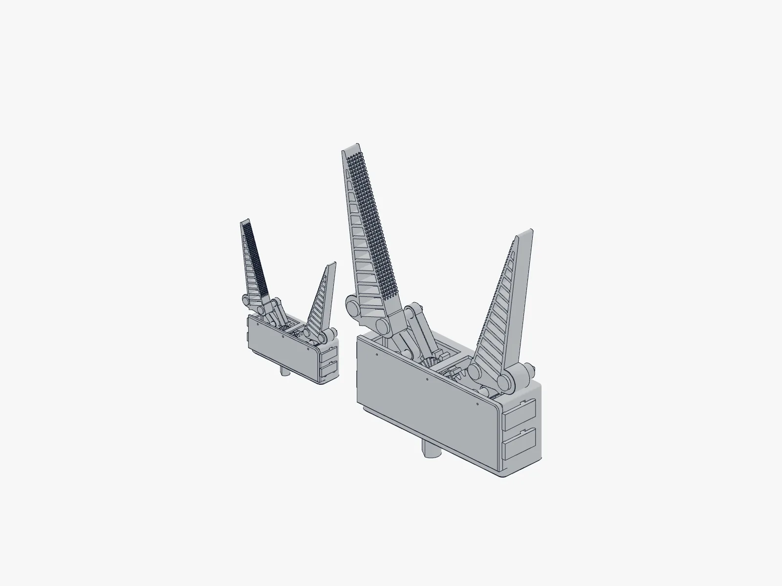
The gripper this document describes is small on purpose. At full open the fingertips part by about 124 millimetres, and the drivetrain delivers well under a newton per finger. That is the right size for the bench and the scaled test objects, but it is too small and too gentle to recover a real amphora, anchor fluke or ballast stone off the seafloor. Every archaeologist we showed it to asked the same question: can you make it bigger?
The answer is yes, and the way we built it means bigger is one parameter, not a redesign. A single scale variable multiplies every linear dimension of the model, and we built and re-simulated two larger sizes from it, 1.5 times and 2.0 times. The linkage, the gears, the finger walls, the enclosure, the input shaft, the mounting flange and the snap clips all scale together, so every ratio and every angle is preserved. We checked it: the finger rotation is identical at all three sizes, and the jaw opening scales exactly.
A few things are held constant on purpose, because they are set by physics or by the printer rather than by the size of the part. The print and running clearances stay at about 0.3 millimetres, because they are governed by the 0.4 mm nozzle, not the part. Fastener sizes stay put, and only the positions of the bolt holes move. The flood and drain hole radii are sized by bubble and surface-tension physics, so they hold while their positions scale.